
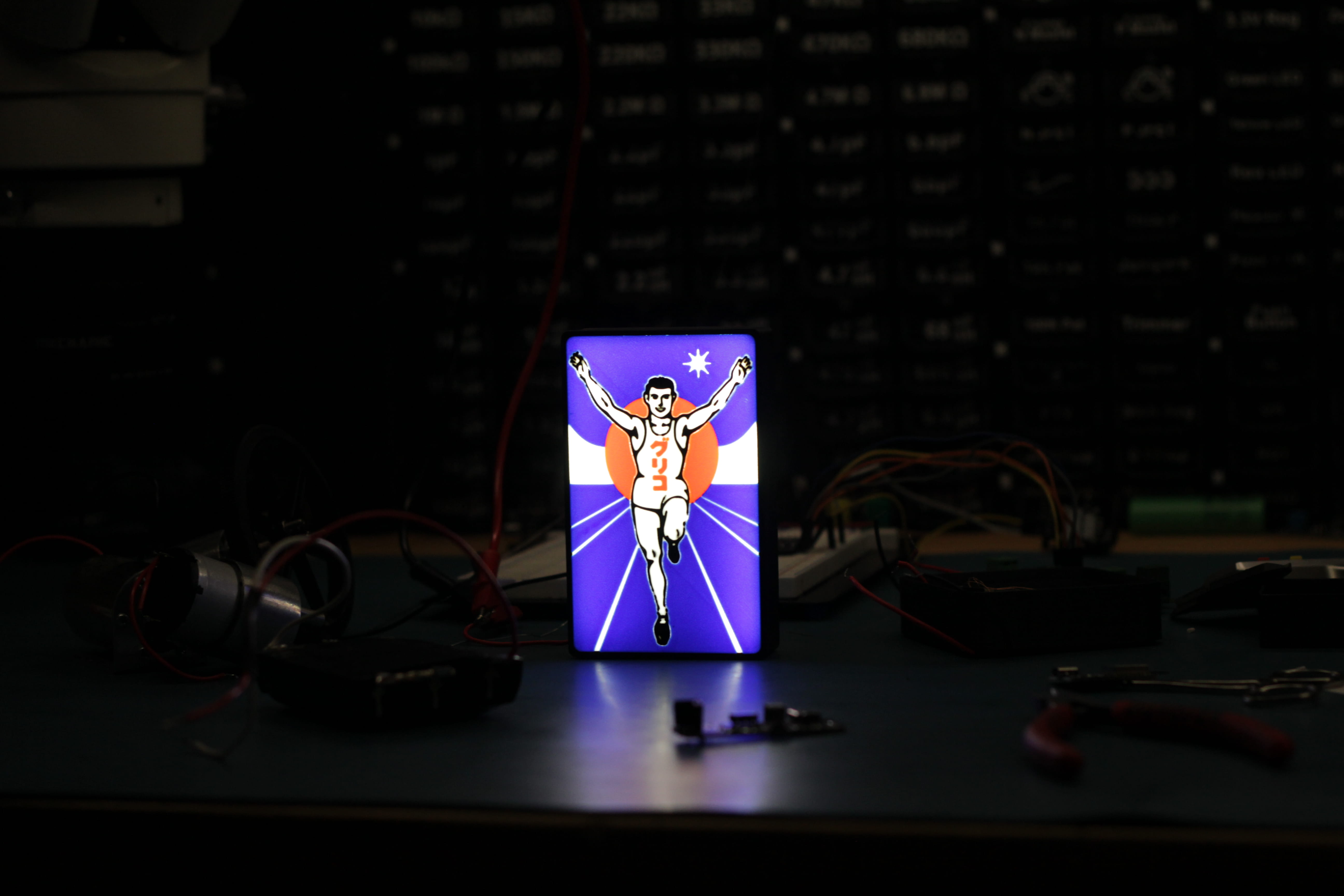
Ever had some sort of display sitting on your desk and by the time you turn the lights off and get into bed, you look at it shining directly back at you? if only there was a way to automatically switch it off. Given that I was studying EGB348 (Electronics) a course on Transistors and MOSFETS. I had the idea of using that knowledge to make a light box that could actively turn on or off depending on the light level within the room. Using a microprocessor would've been easier, but that's more of a coding challenge than electrical, so I stuck with analogue.
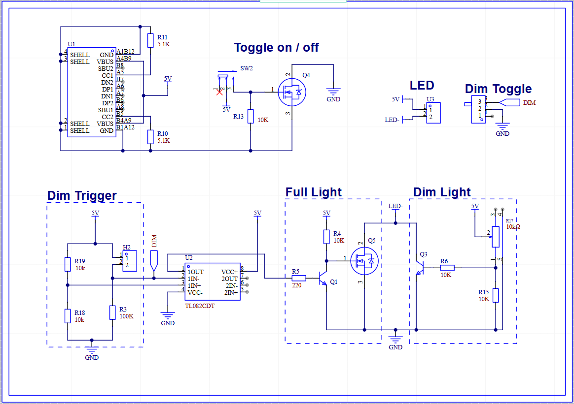
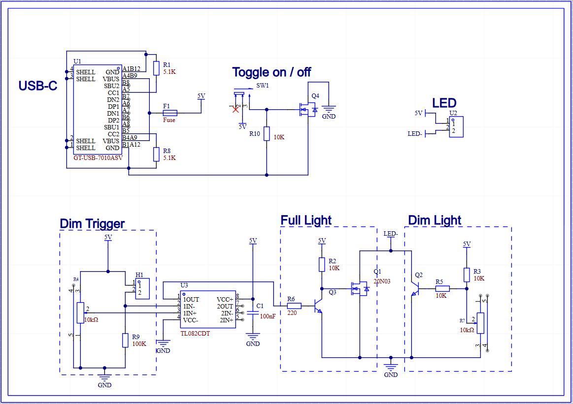
Figure 1 represents the first iteration of the driver. USB-C for power delivery, 5V input and a max current delivery of 3A allowed for 15W of total power. With the toggle switched rated for 100mA, running the current through a NFET who's Vgs was controlled by the toggle switch was the best choice.
Using an op-amp in a comparator configuration allowed the LDR (Light Dependent Resistor) to control the output of the op-amp. Q1, the NPN BJT had two uses, first was flipping the logic, to correctly turn OFF the light when Vn > Vp. The second reason was to allow the Vgs of the NFET to reach 5V. My original choice of op-amp was not rail-to-rail. The output of the op-amp was around 3.8V, that would have increased the RDSON. The LED is always on due to a heavily current limited path via Q3, this gives the dim light effect that is appropriate for a dark room. The intensity in dim mode is controlled via R17, a 10k potentiometer. Users that always want the light to be on, easily ground Vn via a sliding switch.
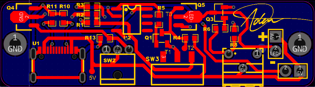
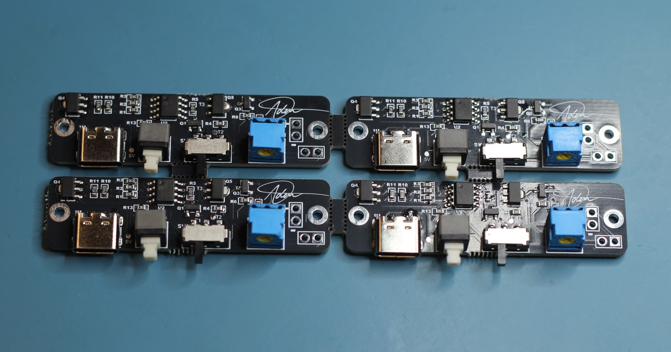
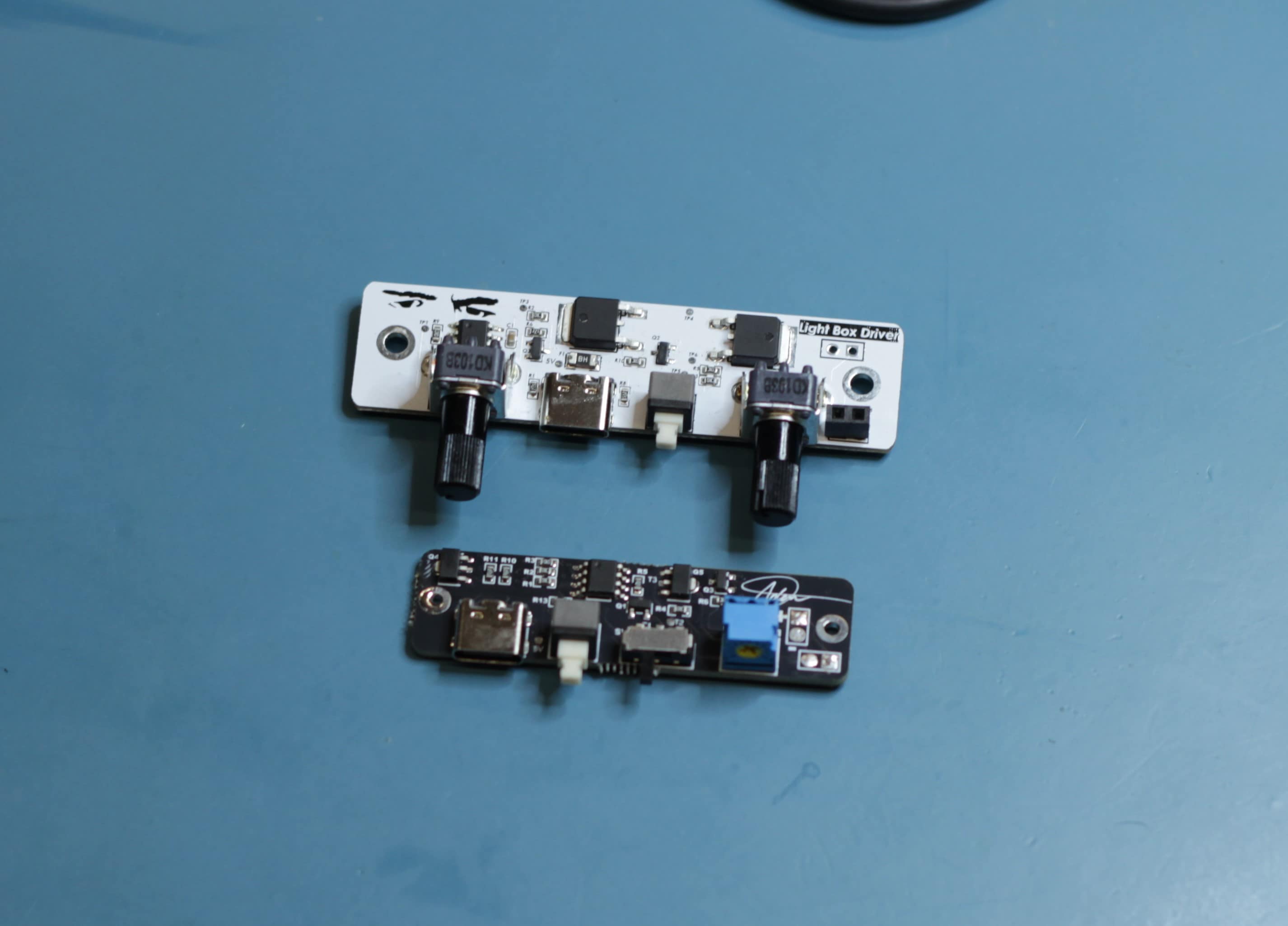
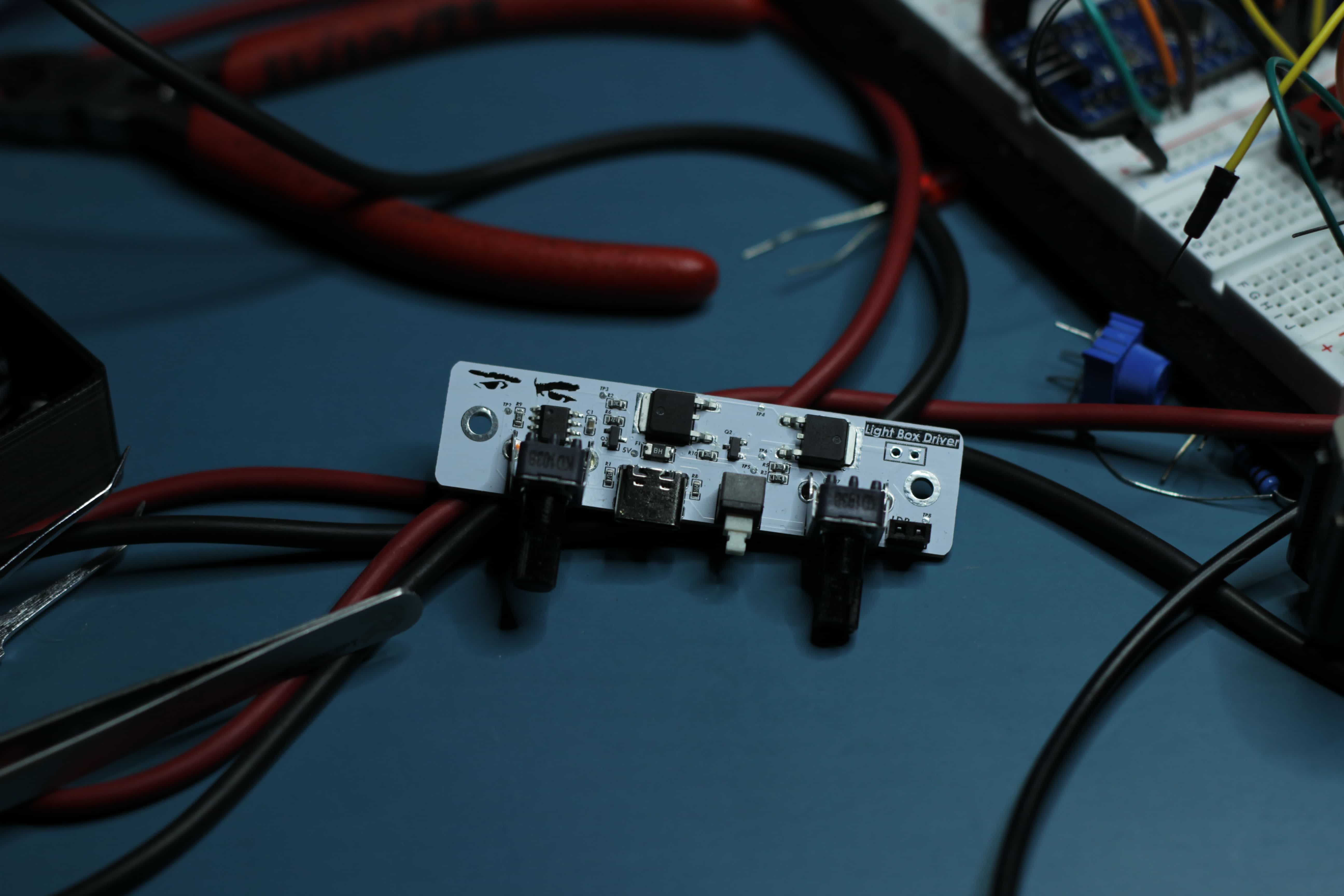
The PCB worked fine, but I decided to update the design a little bit. Turns out there's a big difference between a potentiometer and trimmer potentiometer in terms of life cycle (100 vs 10,000). Not only that, but I wanted to user to be able to set the light level at which the light would dim. If someone had the light box right next to a wall, the LDR would be in a dark spot, causing the light to never turn on. I decided to upgrade the NFET's for better power dissipation, may as well design the PCB to take the maximum 15W USB-C can offer, as well as using a white PCB to help reflect light internally. Below is the updated design.
From the video above, you can see the LDR voltage (Purple) and the dim trigger voltage (Yellow). The left potentiometer controls the brightness of the light in dim mode. If VLDR is greater than VDIM the light will be fully lit.