
One of the units I did this semester (EGB240 Electronic Design) went into depth on filtering. High Pass, Low Pass, First Order, Second Order filters. The final examination on the unit was a practical one, in which you given a PCB with a schematic and you used an oscilloscope to test each stage of the filter to figure out its characteristics.
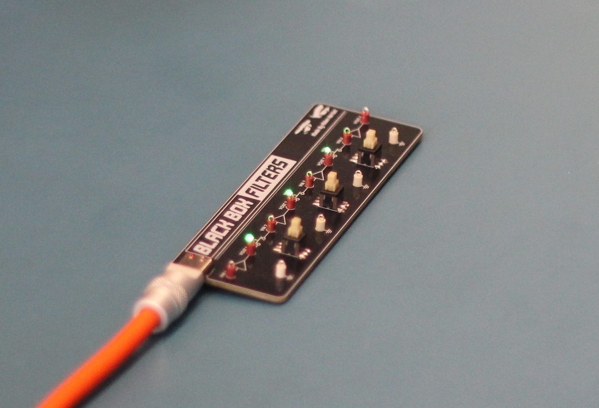
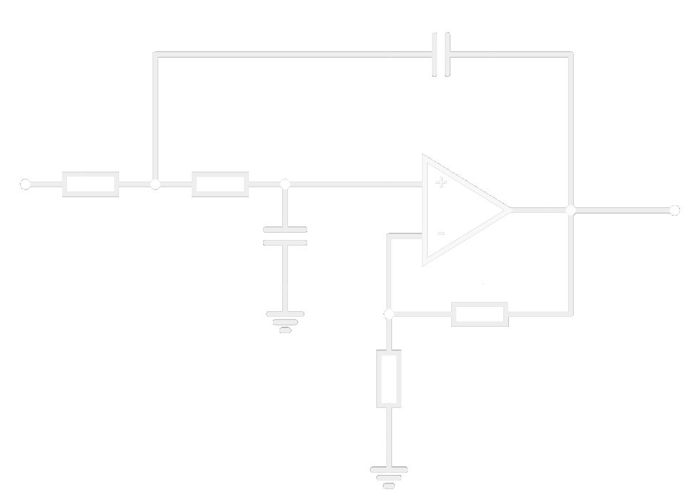
I decided to make the board they would give us on the exam to practice for it. Using an Sallen-Key Topogology (non-unity gain), you can make all the filters that were introduced into the unit. Swapping the capacitors and resistors would change it to either a High Pass / Low Pass filter. Leaving some components off while shorting others with 0 ohm resistors allowed for first order filters to be made.
With only haviung a short time before the end of semester and the exam, I rushed to get it made, as shipping would take at least a week for the components and PCBS. This lead to one slight error I made which was not having dedicated footprints to allow for reference grounds. With capacitors removing DC biasing, sometimes a 2.5V reference ground was required. But thats okay, little bit of bodge wire never hurt anyone .
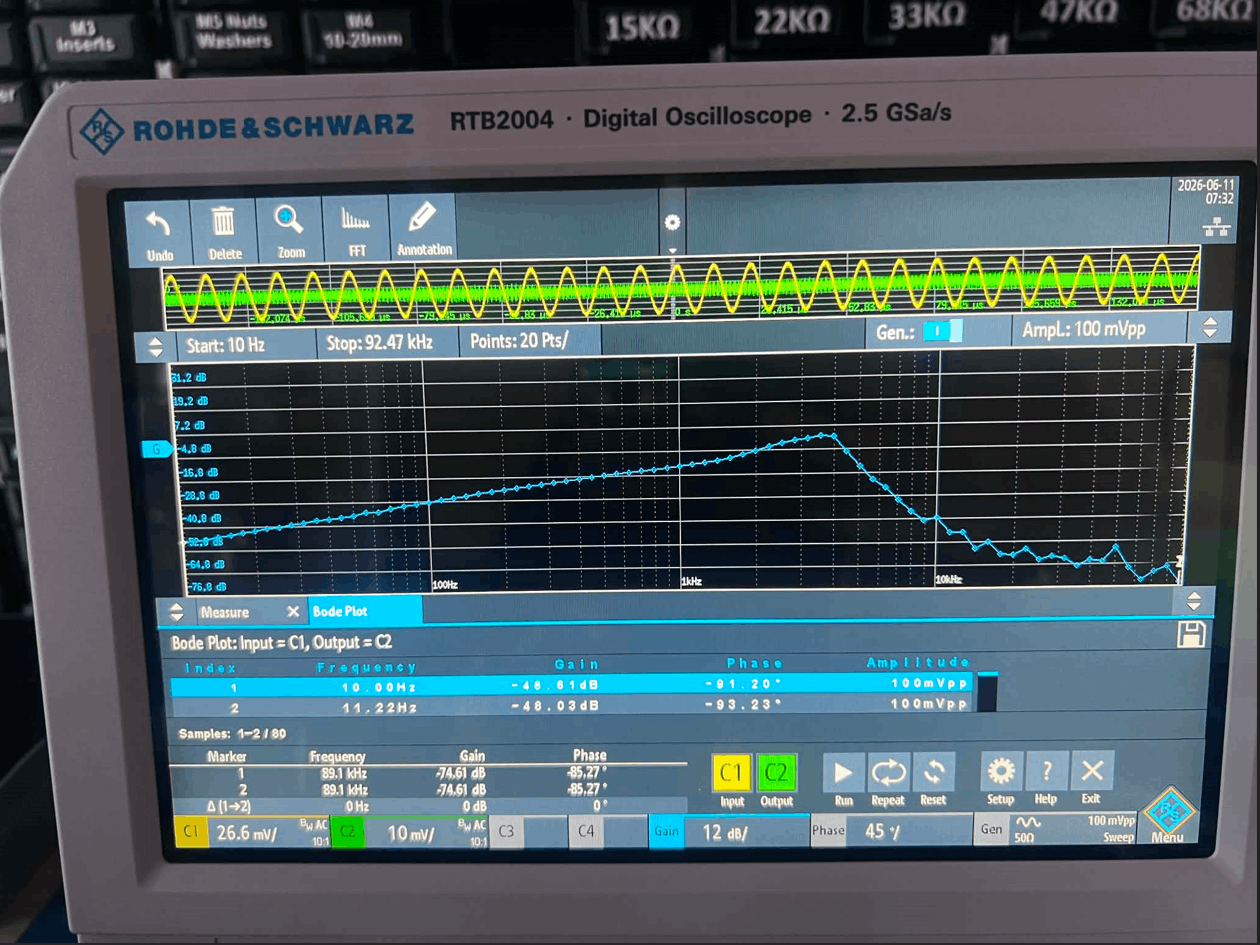
Some bode plot testing with a mix of high and low pass testing.